A Cone Morse releaser for the Sieg X2P Mill
Tired of hammeing the drawbar or my collet holder, and being sure that it was the right way to shorten the life of bearings and vertivcal ways I decided it was time to do something to have a better ( and somewhat ) easier way to release them.
The idea has been freely adapted from a George McLatchie's project on Model Engineers' Workshow ( aka MEW ) #96 ( February/March 2004 ).
He had the idea to build an extractor that screws on the exposed thread above the spindle nut of the mill.
Unfortunately on my mill there is no such threads exposed so I had to find another way !
So I decided to make a new nuw that screw on the spindle but is external threaded to screw an extractor on it.
Here the general arrangement:

The first step was to prepare a screw to use as test screw for the internal thread )
Here the blank preparation and the screwing process:


The thread is 27x1.5 ( metric ).
Let's check if the thread is fine, by using the lathe nut ( you will discover later that this has been really a bad idea ).
The lathe, the classic 7x10 has two nuts that holds the spindle so I can remove one for some time without the risk of loosing the spindle, while the mill has only one .

The nut fit. Let's go on make the new nut for the mill.
First a bore ( 25mm ) in a 40mm mild steel:

Now the internal threading ( 27x1,5 )

And the test-fit with the previously made screw:

It fits, so it' time to create the thread on the exterior for the extractor.
The thread this time is a 40x1.5 ( custom 😎 )

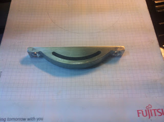
Here the finished nut. Only missing some milling operation:

Now it's time to make the exctractor body. A 50mm M.S. cilinder will accomodate this.
It's really a long time job boring a 38.5mm bore in it, with my little lathe but eventually I finished.
After that, a simple threading operation will complete the interior side:

A little milling operation to create the slot for the spanner:

Here the two parts, ready for testing:


And the extractor assembled:

The idea has been freely adapted from a George McLatchie's project on Model Engineers' Workshow ( aka MEW ) #96 ( February/March 2004 ).
He had the idea to build an extractor that screws on the exposed thread above the spindle nut of the mill.
Unfortunately on my mill there is no such threads exposed so I had to find another way !
So I decided to make a new nuw that screw on the spindle but is external threaded to screw an extractor on it.
Here the general arrangement:

( the descriptions are in Italian, but you get the idea )
The first step was to prepare a screw to use as test screw for the internal thread )
Here the blank preparation and the screwing process:


The thread is 27x1.5 ( metric ).
Let's check if the thread is fine, by using the lathe nut ( you will discover later that this has been really a bad idea ).
The lathe, the classic 7x10 has two nuts that holds the spindle so I can remove one for some time without the risk of loosing the spindle, while the mill has only one .

First a bore ( 25mm ) in a 40mm mild steel:

Now the internal threading ( 27x1,5 )

And the test-fit with the previously made screw:

The thread this time is a 40x1.5 ( custom 😎 )

Here I'm cutting the new nut, after have finished.
Here the finished nut. Only missing some milling operation:

Now it's time to make the exctractor body. A 50mm M.S. cilinder will accomodate this.
It's really a long time job boring a 38.5mm bore in it, with my little lathe but eventually I finished.
After that, a simple threading operation will complete the interior side:

A little milling operation to create the slot for the spanner:

Here the two parts, ready for testing:

Do you remember when I said it was a bad idea to use the lathe nut for testing ?
Well ! My lathe has a RH nut, while the mill's nut is left handed.
Holy crap ! Believe me I wasn't happy at all !!!!!
Anyway I start over for the dual threaded nut ( no photos, but the operation were almost the same seen up to now , only left had threading ) and after completing and testing I was ready for the next step.
First a bluing operation ( hot blueing ) to keep rust out of the way:

I put the nut in a steel cup filled with brass, over the kitchen, until I got a nice blueing:


and it's time to assemble.
Final shots. The nut in place:

And the extractor assembled:

The way this extractor work is the following: when you have to change the CM insert ( chuck, er25 or whatever ) you unscrew for a couple of turn the drawbar, then you screw the extractor on the nut, you screw the extractor nut until the CM release and finally remove the extractor and the CM.
No more hammering, and fastest releasing from now on.
And, as one of my favorite youtuber says: "until next time.... Getter done ! " ( Hello Keith Fenner :) )
Commenti
Posta un commento