A DIY Bandsaw for the shop-
I needed a bandsaw.
I was really, really tired of cutting stock by hand.
I found an old issue of Model Engineer's Worskshop ( number 2, Autumn 1990 ) that has a nice article on a "seems easy to build" bandsaw and I told me: "why not try to do it ?"
Here the first page of the article:
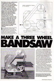
And here the general arrangement:
 Does not seems difficult does it ?
So I started collecting materials.
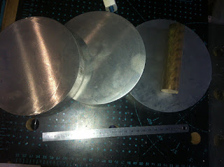
I bought some 160mm aluminium, some bronze for the bushings and some 50x25 steel tubing:


And here you can see how I mounted them on the lathe:

As you can see I'm really pushing my lathe to his limits:

Here I'm creating the channel that will hold the belt that would friction-drive the bandsaw:


In the same way I've created the other two pulley, but more on this later.
I've started boring the drive pulley, and the broaching this one and the drive-friction, as they have a shaft key on the spindle.

And started broaching on the lathe:

It eventually worked, but it was way to slow.


So I decided to make a broach. Here I'm cleaning an unknown piece of steel:

Cutting it:

Cutting the teeth

And here the result. It would not be hardened as it sould be used only on aluminium, and only for two pulleys.

Now I'm turninf the broach guide. 16mm OD, from hot rolled steel.

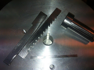
and here all the pieces for the broach. The broach itself, the guide and the shims ( and you can also see the broached pulley )


Now it's time to work on frame. I've extracted my old stick welder ( very old )...


Welding:

Cleaning:

And the results. Not the best weld, but I hope they will work:

And that's the frame:

Not too bad, isn't it ?
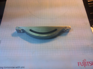
Let's go on. I took an L shaped HRS to create the tensioning mechanism for the rear pulley, opened a couple of holes and cutted the remaining part ( If milled I would have destroyed the end mill on this HSR ):


In this shot you see all the parts for the tensioning system, including the spindle and the bronze bushing :

And in this you can see the spindle and the pulley with the bushing installed.


The block welded:


It starts to look like a real thing, does it ?


On the rotary table to mill away other material.


And here you can read the weight saving. The initial weight was 893 grams, then 690gr ( only the three hole ) then 560 gr ( first face milled ) and finally 480gr ( both faces milled ).

I bought some gear


Preparea a couple of plates to create a gear-box

Bored out the holes to snug fit for the bearings


( all the components for the gear box )

Trial fit

Another shwo for the trial fit


The distance regulation plate:

And the drive pulley.


And this is the cover:


... a nice box for the on-off switch


.. and give a professional look to the whole ensamble:


That's the final result:


I was really, really tired of cutting stock by hand.
I found an old issue of Model Engineer's Worskshop ( number 2, Autumn 1990 ) that has a nice article on a "seems easy to build" bandsaw and I told me: "why not try to do it ?"
Here the first page of the article:

And here the general arrangement:

So I started collecting materials.
I bought some 160mm aluminium, some bronze for the bushings and some 50x25 steel tubing:


The first step was to turn the three pulley.
They are way too big to be taken on my 7x10 minilathe. At least they are too big to be taken in a chuck so I begin with making three tapped hole to mount them directly on the spindle:
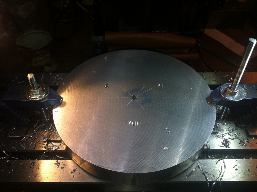

As you can see I'm really pushing my lathe to his limits:

Here I'm creating the channel that will hold the belt that would friction-drive the bandsaw:


In the same way I've created the other two pulley, but more on this later.
I've started boring the drive pulley, and the broaching this one and the drive-friction, as they have a shaft key on the spindle.

And started broaching on the lathe:

It eventually worked, but it was way to slow.


So I decided to make a broach. Here I'm cleaning an unknown piece of steel:

Cutting it:

Cutting the teeth

And here the result. It would not be hardened as it sould be used only on aluminium, and only for two pulleys.

Now I'm turninf the broach guide. 16mm OD, from hot rolled steel.

and here all the pieces for the broach. The broach itself, the guide and the shims ( and you can also see the broached pulley )


This is a shot of the broach in action. I used my vertical drill as a press. It worked ( luckily )

Now it's time to work on frame. I've extracted my old stick welder ( very old )...

And started the welding phase.
Tacking:

Welding:

Cleaning:

And the results. Not the best weld, but I hope they will work:

And that's the frame:
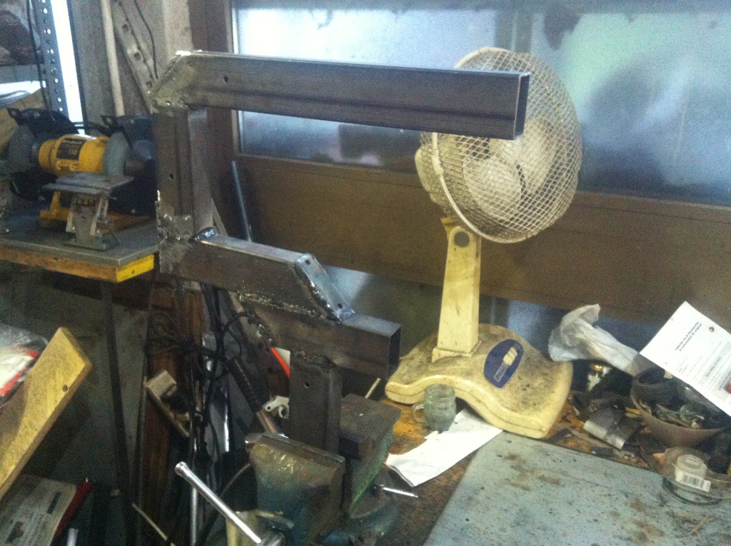
Not too bad, isn't it ?
Let's go on. I took an L shaped HRS to create the tensioning mechanism for the rear pulley, opened a couple of holes and cutted the remaining part ( If milled I would have destroyed the end mill on this HSR ):


And in this you can see the spindle and the pulley with the bushing installed.

I don't have a press, so that's the way I used to press the bushing in the pulley.
A 12mm threaded bar, some washer and two nuts become my press, and they worked well:


Let's now keep on with the central block. This block holds the main spindle that connect


And the table holder in position:

Just a shot of the tilt mechanism:

It's time to get a look at the whole assembly:

The main problem now is that it's very heavy, while my idea is to be able to move it aroud without to much problems. Let' s see if I can make it lighter.
I decided to lightening the pulley:


On the rotary table to mill away other material.


And here you can read the weight saving. The initial weight was 893 grams, then 690gr ( only the three hole ) then 560 gr ( first face milled ) and finally 480gr ( both faces milled ).

Not bad, almost half of the weight saved. Multiplied for two pulley means almost 1kg saved.
Now it's time to find a way to reduce the motor speed. I decided to use an old "Pastamatic" motor and it should have enough torque and it' relativelly small. The problem is that it has 2700rpm, and I need to have no more than 100rpm. Thus I need to reduce the rpms mechanically, and this would give a plus, as reducing the speed I can have a bit more torque.

turned down to save some weight and space

Preparea a couple of plates to create a gear-box


Prepared the spindles


( all the components for the gear box )

Trial fit

Another shwo for the trial fit

And the gearbox assembled. No unwanted play, no bindings.

And finally the wedding ( wedding is a term used in automotive production, when the engine is joined to the chassis )


The distance regulation plate:

And the drive pulley.

A bit ot math, for those interessed:
I had a 2700 rpm motor, and the final drive ( belt ) was 4/1 reduction.
So 2700 divided by 4 was 692,5 rpm. The gear bos has the following gears:
20-60-20-61 ( the 60 gear was finished, and I didn't want to wait :) ).
Thus I have:
2700 / 3 = 900 rpm
900 / 3.05 = 295.xxx rpm
295/4 = 73.xxx rpm, which is in my target.
Just in case you wander, the rotation was on the wrong direction, but and idler 20t gear solved the problem 😄.
This is the first shot with a bandsaw installed. The bandsaw is 1470mm lenght:

I'm at the magic moment when "she" starts help building herself.
Let's keep swarf outside the gearbox. I built a very easy pressbrake to form a steel sheet:


And this is the cover:


Now it's the time to create a bandsaw guide with a couple of bearing:


.. make the blade covers

... a nice box for the on-off switch


.. and give a professional look to the whole ensamble:
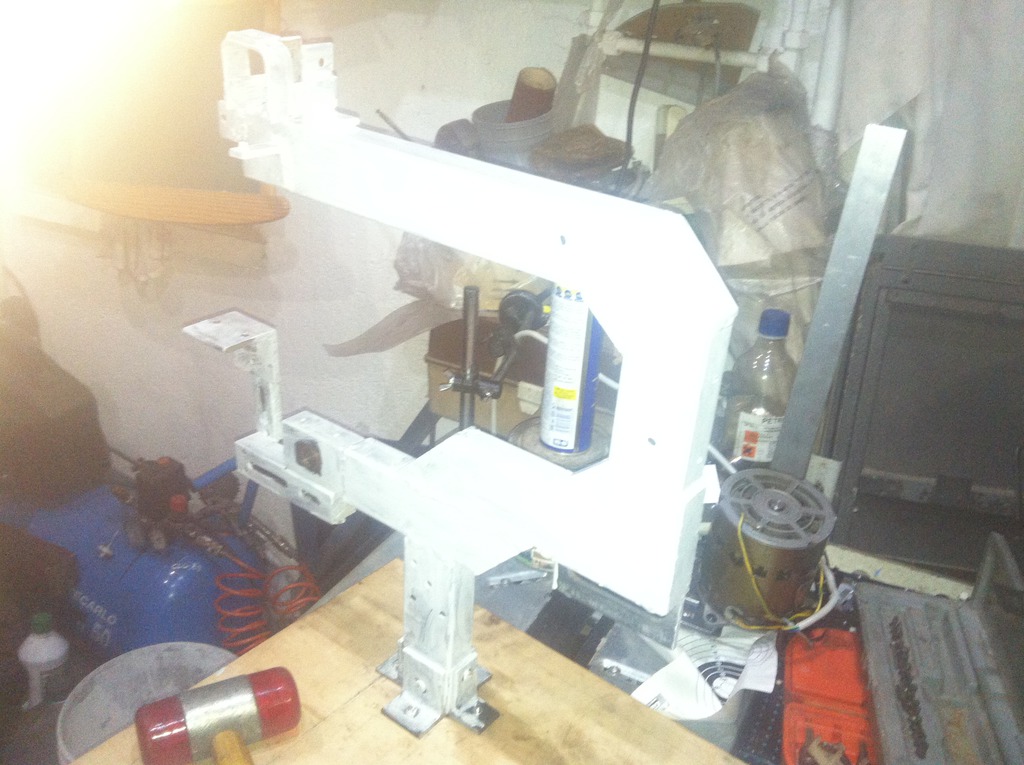

That's the final result:

Let's try it with a 50x25 CR steel :

It seems to work.
If you want to see some short video footage have a look at thess youtube videos.
Very first run:
First cut, a 30x30x3 HRS angle
And a complete tour of the finished "produtct":
Conclusions:
It took me from may to december 2016 from start to finish, working in the evening and not all days, but It greatly improved a lot of my knowledge in al lot of metal working areas.
I spent ( I don't exactly remember ) some 50/75 Euro for the raw stock, material, and maybe another 25/40 for motor and other stuff. Being that here in Italy a little bandsaw, but with similar rigidity and capability would cost not less that 300 Euro, I think I reached my target, and more over I spent 8 month by really amusing myself.
If I wer to build it again there are really few thing I would change. Maybe I will find a better motor but the basic project was ( is ) really good.
I still need to build something to keep swarf out of the main spindle as one day one little piece of swarf get trapped in the bushing and blocked everything.
I had to undo the main drive, clean it on the lathe, clean the bushing and redo her again, but since the date of finishing I have used her for almost everything and cutted I think almost 100kg of steel in every size and dimension, not speaking of aluminium, wood, plastic, fiberglass and every other material I need to cut and she is still running well.
If you have some question I will be happy to answer.
Commenti
Posta un commento